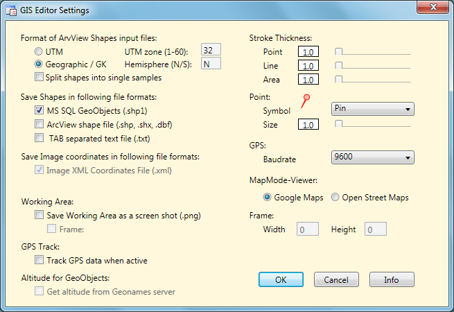
Pressing the Settings button
in the Control Panel will open a dialog to adjust these GIS Editor settings which are not frequently
changed:
ArcView is a common
Desktop GIS tool and stores its data in binary files. The GIS Editor is able to read
these files and display the included geography objects. But because ArcView does
not necessarily provide a dedicated information about the GIS format of the contained data,
the user has to know and select it in advance.
The GIS Editor currently supports WGS84 geographic coordinates, Gauß-Krüger coordinates
(Potsdam datum) und WGS84 UTM coordinates. If "Geographic / GK" is selected, the
program will choose the right format by checking the binary values. In case of UTM
the user must select the hemisphere (N/S) and the UTM zone (1-60) to ensure that
the objects will be displayed at the correct location.
The ArcView data files may contain complex geographic shapes (e.g. polygons or line strings) which are combined by the GIS editor to one multi object (e.g. multipolygon) by default. To split up the shapes into single objects the option "Split shapes into single samples" has to be selected. Then they are placed into the sample list separately. This could be helpful to avoid out-of-memory errors if very large shapes should be converted to SQL geography strings.
At the moment 3 formats for object files are supported:
Microsoft SQL Geo Objects
are part of a standard for storing geometry and geography data in an SQL database,
as used by the DiversityWorkbench modules. They are a well defined text string
containing the geometrical type (e.g. Polygon, Line, Point) and the geographical
coordinates (longitude, latitude, optional altitude) of an object.
Together with the GIS Editor attributes (e.g. color, transparency) they are stored
in a proprietary GIS Editor shape file in ASCII text format. This file can easily
be read and changed using a text editor.
TAB separated text files are widely used as an interchange data file format. The content of a file is more or less the same as above, but the parameters of each object are placed in a single text line, separated by tabulator characters. Additionally to the SQL Geo Object the "envelope center point" (longitude and latitude) of it is saved separately in the file.
The GIS Editor can also create ArcView compatible files to store the samples, which then may be read from ArcView GIS tools. 3 files are required for each type of shape: A data file with extension ".shp", an index file with extension ".shx" and a description file in dBase format with extension ".dbf".
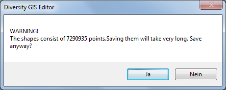
The advantage of the first format is the transparency and readability of the data file, which is just one single text file. But storing huge samples is time consuming, because they have to be converted to SQL geography strings. If the samples consist of more than 100,000 points, an warning message is shown and the user may decide whether to continue or not:
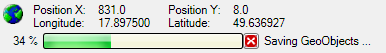
While saving the shapes, a progress bar will be displayed to indicate the status of the task:
Using the ArcView format makes the data files compatible with many applications. Huge samples can be stored much faster. But each type of sample requires a separate set of output files, because different types of objects within one file are not supported so far. So a sample list containing 10 objects will produce 30 data files (file name with an appended index, which is incremented for each sample). Furthermore the attributes like color, transparency and stroke thickness will not be saved.
Currently there is just one format supported for storing image coordinates. They are written into an XML file which is also used in DiversityMobile modules. Saving the coordinates in this format is required for the GIS Editor, so it cannot be disabled.
Selecting this check box and later on pressing the Save button
will additionally scan the working area including all visible objects
and save it as an image file under the name provided in the save file dialog, see
Save Samples.
This is useful for documentations.
Note: There are copyright restrictions on maps or aerial images which are
created with the Google maps viewer. Please contact Google before using them for
publications to grant a license, or use Open Street Maps captures, which could be
used freely under the
Creative Commons Attribution Share Alike license
 conditions.
When checking the "Frame" box just a rectangular part of the working area is saved. The size (in pixels) of the frame has to be defined in the adjacent "Width" and "Height" fields. This is convenient if the resulting image should have well defined dimensions, e.g. fit the resolution of a smartphone display. This feature is only active when the Save Working Area box is checked. After closing the Settings window a rectangular frame of these dimensions is displayed on the working area which defines the part to be saved.
When checking this box the movement of the GPS marker on the background map will be tracked by a line string. After switching off the GPS button the line string will be added to the sample list automatically.
This box applies to MS-SQL Geo Objects only. If checked, the appropriate altitude of the object points (longitude, latitude) will be stored in the file, too. This is not recommended for sample objects with a lot of points or vertices, because for every point the Geonames server has to be contacted to request the associated altitude value. This could slow down the saving procedure immensely.
The stroke thickness for area, line strings and point symbols can be set by using the appropriate slider. The value of the thickness is shown in the label box left of the slider. Double clicking the slider will reset the thickness to its default value 1.
The symbol for the points can be selected from the drop down menu. The symbol size can be set using the slider below the menu. The point symbol display will change accordingly.
It is essential to set a suitable baudrate for a connected GPS device according to its specification. The rate can be selected from the list of the drop down menu. If no GPS device is available, Demo mode could be chosen to see the behaviour of the functionality.
The radio buttons offer the choice of the viewer for creating a background map. Currently Google Maps and Open Street Maps are provided.
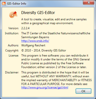
Clicking the Info button will display a window containing GIS Editor version and license information.
Finally pressing the OK Button will save the settings, pressing the Cancel button will discard them.